Special Pins
Omega2 devices have special pins that require consideration at design time:
- System boot pins that affect the boot sequence
- SPI pins used by onboard flash
- GPIOs that control the Omega LED and Reset pins
- Other pins of note
System boot pins
There are seven pins that affect the Omega’s boot sequence and require special attention. The pins fall into two categories:
Floating:
These pins must be floating at boot time. They cannot be pulled up or pulled down, or else the Omega will not boot.
Floating or pulled down:
These pins must be floating or pulled down at boot time. They cannot be pulled up during the boot sequence or else the Omega will not boot.
Once the Omega device has been booted, these pins can be used normally.
| GPIO | Description | Boot Time |
|---|---|---|
| GPIO1 | GPIO / I2S SDO | Must be floating or pulled down |
| GPIO6 | SPI CS1/ GPIO | Must be floating |
| GPIO7 | SPI CLK | Must be floating |
| GPIO8 | SPI MOSI | Must be floating |
| GPIO12 | UART TX0 | Must be floating or pulled down |
| GPIO45 | UART TX1 / GPIO | Must be floating |
| GPIO36 | GPIO / PERST_N (Omega2S Only) | Must be floating |
SPI pins
The Omega’s processor communicates with the onboard SPI flash storage using Chip Select 0 on the Omega’s SPI bus. Since there are two SPI chip select signals it’s possible to connect an additional SPI device to the Omega using Chip Select 1. As such, the SPI communication pins - CLK, MOSI, and MISO - are exposed on the Omega2's expansion header as GPIOs 7, 8, and 9.
Since the Omega’s storage uses SPI, the SPI communication pins - GPIOs 7, 8, and 9 - must be used for the SPI protocol and cannot be used as regular GPIOs. These GPIOs are reserved for SPI devices and will use Chip Select 1, on GPIO6, as their chip select signal on the Omega’s SPI bus.
| Name | I/O | Description |
|---|---|---|
| SPI CS1 | I/O | SPI Chip Select 1 |
| SPI_CLK | O | SPI Clock (Cannot be used as a regular GPIO) |
| SPI_MISO | I | SPI Master Input/Slave Output(Cannot be used as a regular GPIO) |
| SPI_MOSI | O | SPI Master Output/Slave Input (Cannot be used as a regular GPIO) |
| SPI_CS0 | O | SPI Chip Select 0. Only exposed on Omega2S. (Cannot be used as a regular GPIO) |
Imortant Notes:
- GPIOs 7, 8, and 9 can only be used for the SPI bus and cannot be used as regular GPIOs.
- Connecting non-SPI circuitry to these pins may prevent your Omega from booting or could damage the device.
- The SPI CS1 pin, GPIO 6, may be used to control an additional external SPI device.
- The SPI CS1 pin, GPIO 6, may still be used as a regular GPIO when configured as a GPIO using
omega2-ctrl.
For more information on GPIOs and Pins, see the pin multiplexing article.
Reset pins
The Omega’s hardware design uses dedicated GPIOs to control the Omega’s LED and accept an incoming Reset signal:
| Name | I/O | Function |
|---|---|---|
| GPIO38 / SW_RST | I/O | FW_RST Active-High |
| HW_RST_N | I | HW_RST Active-Low |
Soft reset
The GPIO38 pin acts as the soft reset on the Omega2. It is configured in the Onion Omega2 firmware to be the programmable user input button. By default, the input is configured active-high and will trigger a reboot of the operating system.
Hard reset
The HW_RST_N pin acts as the hard reset on the Omega2S. This input is active-low, and, when asserted low, will perform a hard reset (a power cycle) of the CPU.
Special reboot considerations when using HW_RST_N
Both the Omega2+ CPU and the Flash memory boot from a 3 byte address mode. During a reboot the Flash memory and CPU upgrade to a 4 byte address mode to access higher memory addresses.
During an unexpected reset (brownout) the CPU resets, but the memory remains in the 4 Byte address mode. This mismatch prevents the CPU from booting normally. A hard reset (power cycle) will reset the Flash memory back to a 3 Byte address mode and the system will boot normally.
Different boot conditions
| Boot State | GPIO 6 (SPI CS1) State | CPU address mode | Flash address mode | Boot Result |
|---|---|---|---|---|
| Cold boot | Default (pull down) | 3 Byte | 3 Byte | Success |
| Hot boot | Default (pull down) | 3 Byte | 4 Byte | Fail |
| Cold boot | Pull up | 4 Byte | 3 Byte | Fail |
| Hot boot | Pull up | 4 Byte | 4 Byte | Success |
GPIO6 & GPIO11 HW_RST_N requirements
Based on the table above, we need to have the GPIO 6 pulled down during a cold boot and pulled up during a hot boot, for the system to boot successfully. The following circuit does just that.
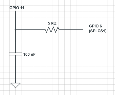
- During a cold boot, GPIO 11 starts as LOW and GPIO 6 reads LOW.
- During a normal boot, the boot loader sets GPIO 11 to HIGH, which charges the capacitor to 3.3V.
- During an unexpected reset or hot boot, the capacitor temporarily pulls GPIO 6 to HIGH, setting the CPU to boot from a 4 Byte address mode.
LED pins
The Omega uses a dedicated GPIO to control the status LED:
| GPIO | Function | Omega2/Omega2+ | Omega2S Pin Number |
|---|---|---|---|
| GPIO44 | Omega Status LED | No, connected to onboard LED | 19 |
Differences between Omega2/2+ vs Omega2S/2S+
- On the Omega2/Omega2+, the pin is not exposed but directly connected to an onboard LED.
- On the Omega2S/2S+, the pin is exposed.
Pin behavior during boot
Omegas’a bootloader governs pin behavior. Most of Omega’s pins will remain at the default digital low state during the boot process. There is one pin that behaves differently. The GPIO 11 pin will settle at digital high. Previously, this pin provided power for the reset button on the Omega docks.
| GPIO | Behavior |
|---|---|
| GPIO11 | Will settle at Digital High - Previously used to provide power for the reset button on Omega2 Docks |
The Omega2 bootloader is open source and can be found on GitHub: OnionIoT/omega2-bootloader.