One-Wire
One-Wire devices include, but are not limited to, temperature loggers, battery monitors, humidity sensors, and voltage and current sensors. They can be used with the Omega2 family of modules using the One-wire communication protocol.
Context
The following sections discuss what a One-Wire device is, and the communication protocol used by all One-Wire devices.
What is a One-Wire device
A One-Wire device is an electronic component that communicates using the One-Wire protocol, enabling communication with a host system using a single data line. These components are specifically designed to function on a One-Wire bus and can contain an array of integrated circuits (ICs) such as sensors, memory chips, or other peripherals.
Every One-Wire device connected to a network has its unique 64-bit address (a.k.a ROM code), enabling the host system to communicate with any specific device(s) on the One-Wire bus.
What is the One-Wire protocol
The One-Wire protocol is a communication protocol that establishes a low-speed communication bridge between One-Wire devices and processors/micro-controllers over a single data line. With a single data line as a communication methodology, the wiring process is tremendously simplified, and the number of pins required to bridge the connection is also reduced.
One Wire protocol follows a master-worker architecture with each bus allowing for one master, in this case, an Omega2 board, and a worker device like the DS18B20 temperature sensor.
Hardware
Support for one-wire devices on the Omega2 is enabled with a Device Tree Overlay - a run-time modification to the kernel’s live tree.
Onion provides a device tree overlay package for one-wire support. The one-wire bus master is set to GPIO2 in this example package. You can change the setting of the bus master by creating a custom version of the one-wire device tree package.
See the Device tree overlay chapter for further details.
Connect a One-Wire device to the Omega2
This section covers a three-stage process for establishing the physical wiring connection of your One-Wire device to GPIO2, where the latter will serve the role of the One-Wire master.
Stage 1: Identify the Connectors
One-Wire devices require three connections as illustrated in the table below:
| Wire | Connection |
|---|---|
| VCC | Connect this wire to the 3.3V power source on the Omega2 board. |
| GND | Connect this wire to the ground pin on the Omega2 board. |
| DQ | Connect this wire to the GPIO2 pin on the Omega2 board. |
One-Wire device circuit diagram
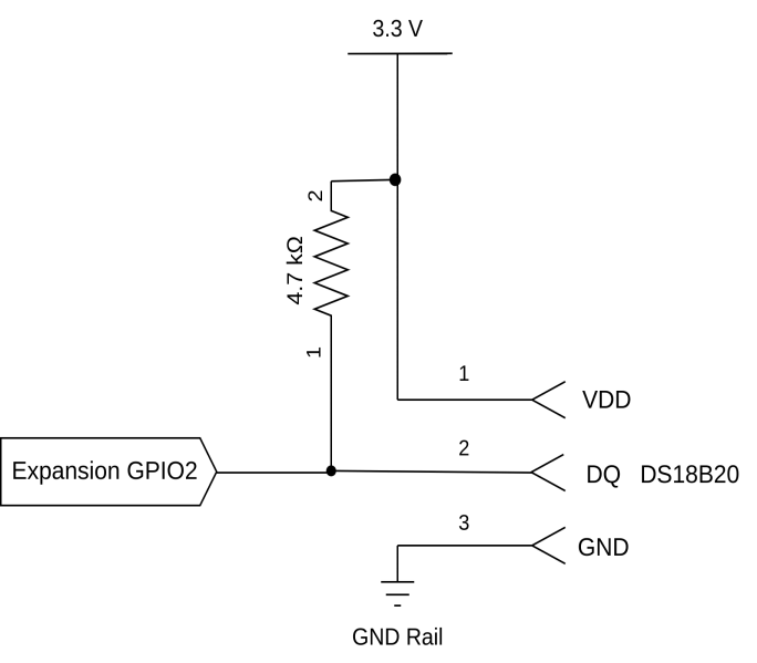
Note: Please refer to your specific One-Wire device's datasheet to identify the pins and determine the recommended voltage.
Some One-Wire devices will require a pull-up resistor on the Data line (DQ). For example, the popular DS18B20 temperature sensor requires a 4.7 kΩ pull-up resistor on the DQ to operate properly.
Stage 2: Connect Power & Ground
Connect the power and ground wires belonging to your One-Wire device to the corresponding power and ground pins on the Omega2 board.
Stage 3: Connect the DQ
Connect the DQ from your One-Wire device to the GPIO2 pin on the Omega2 board.
Software
The following sections discuss how to install and work with the software used to communicate with One-Wire devices.
Enable One-Wire device support
Once the physical connections are made, install the dts overlay package to register a one-wire master in Linux associated with GPIO2 to communicate with the one-wire worker device.
Step 1: Update the packages list using opkg.
opkg update
Step 2: Install the onion-dt-overlay-w1-gpio package using opkg.
opkg install onion-dt-overlay-w1-gpio
Step 3: After the package is successfully installed, GPIO2 will act as a One-Wire Master.
/sys/devices/w1_bus_master1
Find connected One-Wire devices
Step 1: Navigate to the relevant directory where One-Wire devices are listed. This is under /sys/devices/w1_bus_master1.
cd /sys/devices/w1_bus_master1
ls
Step 2: Perform a check to find if slave devices are connected or not.
cat /sys/devices/w1_bus_master1/w1_master_slave_count
Step 3: The command in step 2 will return the count of the number of slave devices connected.
| Result | Interpretation |
|---|---|
| 0 | No worker devices are connected |
| 1 | A single worker device is connected |
| Any digit greater than 1 | Multiple worker devices are connected. Example: If the result is 3, it means that 3 worker devices are connected. |
The One-Wire bus master kernel module scans the data pin every 10 seconds for new devices connected, if any, hence, it is recommended to wait a little while and try again.
Step 4: If a worker device is connected, run the following command:
cat /sys/devices/w1_bus_master1/w1_master_slaves
This will return a (newline delimited) list of your worker device ID(s).
The one-wire master pin should not be left floating after one-wire support is enabled. It should either be pulled to ground or connected to one or more one-wire devices. This will avoid detecting "ghost one-wire devices".
The DeviceID is the serial number of your One-Wire device. Example of a device ID: 28-000123456789. Each device will have a different serial number, making it complex to use One-Wire devices programmatically.
Please keep a record of the DeviceID as the same ID will be used when reading the data from the connected one-wire device as discussed in the next section.
Read data from a connected One-Wire device
Step 1: Navigate to the specific worker device directory and access the data from the w1_slave file by running the following command:
cat /sys/devices/w1_bus_master1/DeviceID/w1_slave
The DeviceID in the command above is the serial number of your One-Wire device we noted in the previous section. Please refer to Step 4 of the command section "Find connected One-Wire devices" to learn more about finding the "DeviceID".
Assuming the slave device is a temperature sensor "DS18B20", having a serial number- 28-000123456789, the command will be:
cat /sys/devices/w1_bus_master1/28-000123456789/w1_slave
Step 2: The command executed in Step 1 will return the raw data from the connected One-Wire device.
Example of the raw data from the connected temperature sensor like the DS18B20:
b1 01 4b 46 7f ff 0c 10 d8 : crc=d8 YES
b1 01 4b 46 7f ff 0c 10 d8 t=27062
In the sample raw data above, the final t=27062 indicates the temperature is 27.062 ˚C.
Common pitfalls and precautions
Cross-check your wiring to make sure that VCC, GND, and DQ lines are correctly connected because incorrect wiring might lead to communication issues.
Please ensure that the One-wire device’s dataline is connected to GPIO2.
While connecting the One-Wire device to the Omega2 board, refer to the data sheet and documentation for your specific One-Wire device for detailed wiring and configuration instructions.
Some One-Wire devices will require a pull-up resistor on the Data line (DQ). For example, the popular DS18B20 temperature sensor requires a 4.7 kΩ pull-up resistor on the DQ to operate properly.