Omega2S Eval Board
The Omega2S Eval Board is a stand-alone single board computer meant for evaluating and working with the surface-mount Onion Omega2S modules.
It lowers the cost barrier for working with the Omega2S module by providing access to almost all the Omega2S capabilities and I/O, without the need for an expensive development kit. This makes it an essential tool for evaluation, prototyping, and development.
This board can also serve as template for custom designs and even as standalone SBC for custom applications.
Resources
Resources for working the with Omega2S Eval Board
Quickstart Guide
A quickstart guide and an accompanying video is available to help get users up and running with the Omega2S Eval Board.
Hardware Design
The Omega2S Eval Board design is open source and can be found in the OnionIoT/Omega2-Eval-Boards GitHub repo
Hardware
Overview
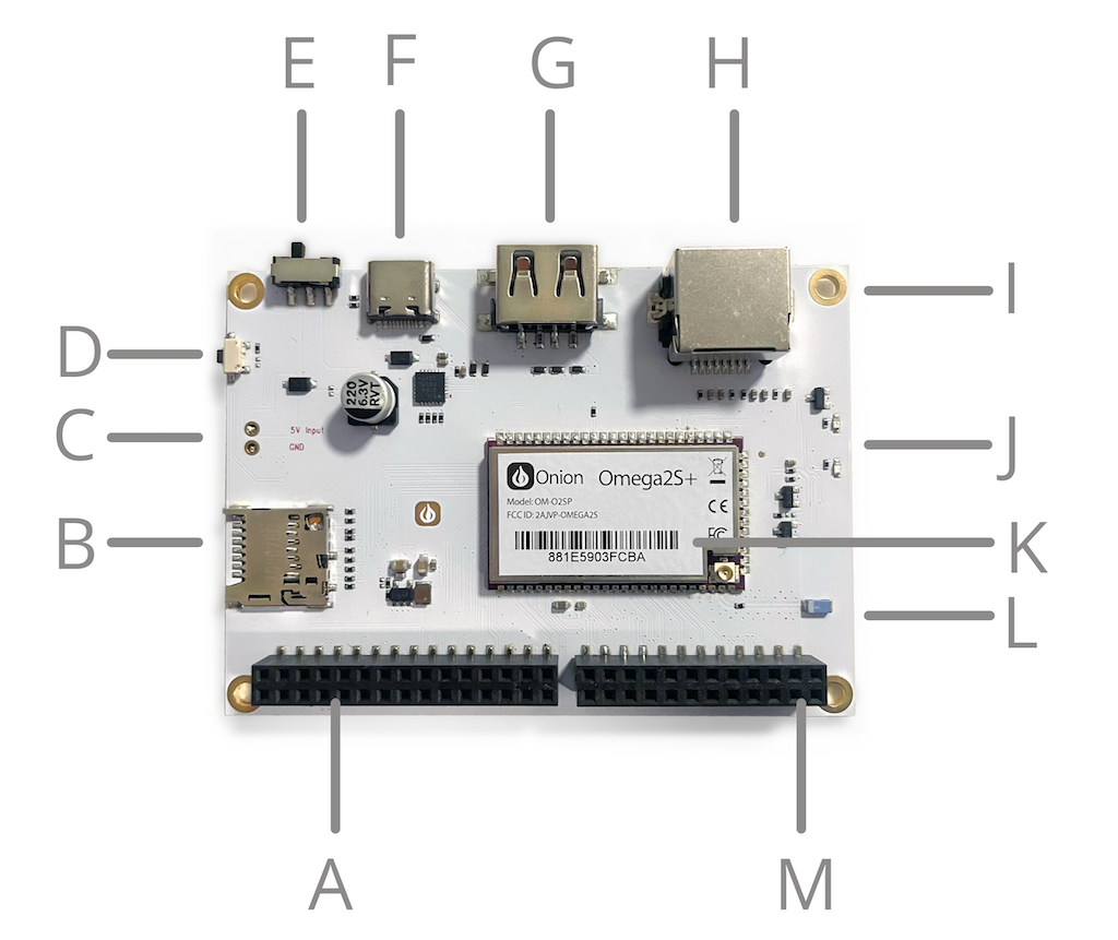
| A. 30-pin I/O Header | H. Ethernet Port |
| B. MicroSD Slot | I. Mounting Hole |
| C. External Power Connector | J. LEDs (Boot status and user programmable) |
| D. Reset Button | K. Omega2S+ Module |
| E. Power Switch | L. WiFi Antenna |
| F. USB-C Port (Power & Serial Command Line) | M. 24-pin I/O Header |
| G. USB Type-A Host Port |
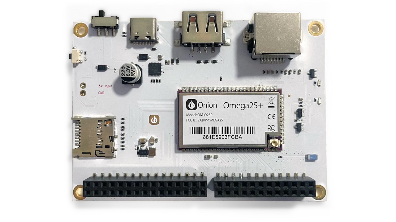
Included on the Omega2S Eval Board is a soldered-down Onion Omega2S+ module (OM-O2SP).
Pins
The Omega2S Eval Board exposes all of the I/O available on the Omega2S through:
- The 30-pin Header (backwards compatible with all Omega2 Expansions)
- The new 24-pin header

For more information on using the Hardware Interfaces chapter on this Documentation site.
USB-C Port
The USB-C port is used to power the Omega2S Eval Board and provide serial access to the Omega's command line.Power
The USB-C port accepts regular 5V USB power and an onboard voltage regulator circuit steps down the voltage to the 3.3V required by the Omega2.
Serial Command Line Access
An on-board USB-to-Serial chip provides always-on access to the serial command line. See the Serial Command Line step in the Quickstart Guide for more information on using the serial command line.
Ethernet Port
The Omega2 has a single 10/100M integrated Ethernet Physical Layer (PHY). The Omega2S Eval Board features an RJ45 Ethernet port to enable easy wired networking.By default, the Ethernet port interface acts as a DCHP client. It expects to receive an IP address from a DHCP server on the network (a router or similar). The Ethernet port interface can also be configured to act as the network host and DHCP host/server, assigning IP addresses to connected clients.
See the article on Ethernet Networking for more details on using the Ethernet port.
USB Type-A Port
The Omega’s USB Port can be used to connect USB devices, anything from cameras to USB storage. The USB port supports USB 2.0, and is a type A connector. See the article on the USB Hardware Interface for more details.
MicroSD Slot
The MicroSD card slot can be used to extend the available storage.
To connect a MicroSD card
- Insert the MicroSD card into the slot
- Secure it by pushing it in until you hear a click
- The Linux operating system will automatically mount the filesystem in the
/mntdirectory
To remove the MicroSD card
- Unmount the SD card filesystem in Linux
- Push down on the card until you hear a click
- Release, and the card will eject
For more information on using the MicroSD card slot, see the SDIO article.
Power Switch
The Power switch controls the power going to the Omega2 module. Use it to manually turn the device on or off.
Note the switch only controls power to the Omega2 module, but not the USB-to-Serial chip. Meaning a connected computer will still detect a USB serial device even when the Omega is powered off, but will it not be able to communicate with the Omega in this case.
Reset Button
The Reset Button is connected directly to the Omega2 Soft Reset pin (GPIO38). Pressing this button does one of two things:
- Reboot
- Factory restore
Reboot
Momentarily pressing the reset button and letting go will initiate a reboot of the Linux operating system.
Factory Restore
Pressing and holding the reset button for 10 seconds then releasing will trigger a factory restore.
A factory restore will reset your Omega to the default filesystem of the last firmware update, this will delete ALL of your data!
Omega2 System Status LED
The amber LED located on the Omega2S Eval Board indicates the current System Status.
It provides a visual indication of its current system state:
- Off – Device not powered on
- Blinking – Booting/updating
- On – Up and running
The Omega2 system status LED is connected to GPIO44. In the Omega2 firmware, the kernel is in control of the LED - meaning it cannot be controlled directly through the GPIO.
User Programmable LED
A blue user programmable LED is built into the Omega2S Eval Board. It is controlled by GPIO43.It is up to the user how to use the LED. In general, a user programmable LED can:
- Show status - For example, to show code is configured, installed, running correctly, or a certain condition has been met
- Help with debugging programs in real-time, where you can program it to blink different patterns based on what code is executing.
See the Hello World demo in the Quickstart guide for an example of using Python to control the user programmable LED.
External Power Connector
There are two 2.54 mm (0.1") spaced through-hole pins for 5V and GND input. This can be used to directly connecting an external power source.
This power connector provides more flexibility for powering the Omega2S Eval Board. The spacing is perfect for soldering down a screw terminal, making it easier to connect external power sources and integrate into various setups.WiFi Antenna
The Omega2 supports 2.4 GHz IEEE 802.11 b/g/n WiFi, and can simultaneously host a WiFi access point and connect to existing WiFi networks.
The on-board antenna is a 2dBi ceramic surface-mount chip antenna, it enables immediate, out of the box WiFi connectivity. A u.FL connector is also featured on the device for users to optionally connect external WiFi antennas.
For more information on the antenna and using the u.FL connector, see the WiFi Antenna & u.FL connector article in the Hardware Interfaces chapter.