Using SPI with Python
This guide will help you quickly get started using the Python spidev module to communicate with SPI devices on the Omega2.
Step 0: Prerequisites
If you haven't already, see the quickstart guide for more information on setting up your Omega2.
This guide assumes:
- The Omega2 is connected to the internet via WiFi or ethernet
- The Omega2 command line can be accessed
All commands listed in the guide should be run directly on the Omega2.
For a deeper dive into the Omega2's SPI functionality, see the SPI article in the Hardware Interfaces chapter.
Step 1: Install Python and the Spidev Module
To use SPI in Python, first install the necessary packages:
opkg update
opkg install python3-light python3-spidev
Step 2: Choose Between Hardware or Software SPI
The Omega2 supports both hardware SPI (using a built-in controller) and software SPI (bit-banging GPIOs). Before proceeding, choose the SPI bus that best suits your needs.
Comparison: Hardware SPI vs. Software SPI on the Omega2
| Feature | Hardware SPI (CS1) | Software SPI |
|---|---|---|
| Speed | Up to 40MHz (fast) | Up to 1.4MHz depending on CPU load - Slower, best for low-data applications |
| Full-Duplex Support | ❌ No | ✅ Yes |
| SPI Configuration | Limited; CS0 is reserved for flash | Flexible; can be configured as needed |
| GPIO Flexibility | Fixed SPI pins (see next step) | Choose from two predefined GPIO sets |
| System Load | Low (uses dedicated SPI controller) | Higher (CPU handles SPI signals) |
Option 1: Using the Hardware SPI Bus (CS1)
The hardware SPI bus is pre-configured on the Omega2 and is accessed through /dev/spidev0.1. It supports high-speed SPI communication but is limited to half-duplex mode and uses the fixed SPI pins:
- GPIO6
- SPI_CLK pin
- SPI_MOSI pin
- SPI_MISO pin
If this setup meets your needs, proceed to Step 3 to connect SPI devices. For most users, this is the quickest option.
Option 2: Enabling a Software SPI Bus
If you need full-duplex SPI, additional SPI buses, or different GPIO assignments, you can enable a software SPI bus by installing one of two available Software SPI Device Tree Overlay packages.
Enabling a Software SPI Bus
To enable a software SPI bus, install one of the following overlay packages:
For an SPI bus on GPIOs 14, 15, 16, and 17:
opkg update
opkg install onion-dt-overlay-sw-spi
For an SPI bus on GPIOs 0, 1, 2, and 3:
opkg update
opkg install onion-dt-overlay-sw-spi-alt
After installation, the software SPI bus will be accessible at /dev/spidev1.0. Note this down for the next steps.
Each package predefines the GPIOs that function as SPI signals. For more details, see the Software SPI Bus article in the Device Tree Overlay chapter.
Next Step: Once you've chosen your SPI bus, proceed to Step 3.
Step 3: Physically Connect an SPI Device
Before we can send data, we need to connect an SPI device to the Omega2's SPI bus.
Pin Connections
If you decided to use hardware SPI in Step 2, connect the SPI pins of your external device to the Omega2 according to this table:
| SPI Signal | Omega2 Pin |
|---|---|
| Clock / SCK | SPI_CLK / GPIO7 |
| MOSI | SPI_MOSI / GPIO8 |
| MISO | SPI_MISO / GPIO9 |
| CS | SPI_CS1 / GPIO6 |
If you decided to use software SPI in Step 2, connect the SPI pins of the external device according to the table below:
| SPI Signal | Omega2 Pin when using onion-dt-overlay-sw-spi | Omega2 Pin when using onion-dt-overlay-sw-spi-alt |
|---|---|---|
| Clock / SCK | GPIO14 | GPIO3 |
| MOSI | GPIO16 | GPIO1 |
| MISO | GPIO15 | GPIO0 |
| CS | GPIO17 | GPIO2 |
Additionally, make sure the SPI device is supplied with power according to its specifications.
Step 4: SPI Hello World - Write Bytes to the Bus
To confirm that the SPI bus is working, we'll run a Python program that writes 256 bytes of incremental data over SPI in eight cycles.
Download the Python Program
To do this, we will first download the writebytes.py example Python proscript from the OnionIoT/python-spidev GitHub repo:
cd /root
wget https://raw.githubusercontent.com/OnionIoT/python-spidev/refs/heads/master/examples/writebytes.py
Software SPI: Change SPI bus in script
If you decided to use a software SPI bus in step 2, the script needs to be updated to use the correct device.
Use the vi editor to modify the change
spi = spidev.SpiDev(0,1)
to
spi = spidev.SpiDev(1,0)
If you're not familiar, the vi text editor is included on the Omega by default. To make the change:
- Run
vi /root/writebytes.py - Enter insert mode by pressing
i - Make the changes
- Return to command mode by pressing
esconce - Save and close the file by typing
:wqand pressing enter
Learn more about the small but powerful vi editor online.
Run the Program
Now, let’s run the script to send data over SPI:
python writebytes.py
This will send 256 bytes of incremental data (0x00, 0x01, 0x02, ...) over SPI, repeating 8 times. If you have a logic analyzer or oscilloscope connected, you should see activity:
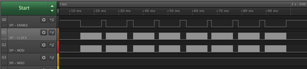 Logic analyzer showing eight blocks of SPI writes
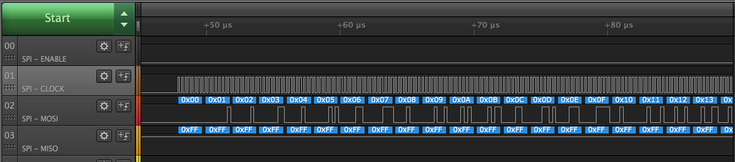
Zooming in, we can confirm the data being sent is incremental:
Step 5: Half-Duplex SPI Transmission
Next, let's run a Python script that performs a half-duplex SPI transaction—meaning it writes a byte and immediately reads a specified number of bytes in return. This is useful for reading registers on an SPI device.
Next, let's run a Python program that performs a half-duplex SPI transaction - meaning it writes a number of bytes and immediately reads a specified number of bytes on the SPI bus. This is useful for reading registers on an SPI device.
Download the Python Program
Download the xfer3.py example script from the OnionIoT/python-spidev GitHub repo:
cd /root
wget https://raw.githubusercontent.com/OnionIoT/python-spidev/refs/heads/master/examples/xfer3.py
Inspect the Program
Before running it, let's take a look at the script using the built-in vi text editor:
vi xfer3.py
We can see the program does the following:
- Opens SPI device 1 on bus 0, meaning it uses the CS1 chip select line on the SPI hardware bus
- Sets the SPI bus speed to 4MHz
- Performs a half-duplex transaction:
- Writes 1 byte:
0x42 - Reads 2 bytes
- Writes 1 byte:
- Prints the two bytes that were read
This kind of transaction is useful when interacting with SPI devices that store data in registers. In this example, the script reads two bytes from the register at address 0x42.
To exit the vi editor without saving changes, type :q! and press Enter.
Software SPI: Change SPI bus in script
If you decided to use a software SPI bus in step 2, the script needs to be updated to use the correct device.
Use the vi editor to modify the change
spi = spidev.SpiDev(0,1)
to
spi = spidev.SpiDev(1,0)
If you're not familiar, the vi text editor is included on the Omega by default. To make the change:
- Run
vi /root/xfer3.py - Enter insert mode by pressing
i - Make the changes
- Return to command mode by pressing
esconce - Save and close the file by typing
:wqand pressing enter
Learn more about the small but powerful vi editor online.
Run the Program
How, execute the script:
python xfer3.py
Observe the Output
The program will display the received bytes on the terminal:
root@Omega-FB94:~# python xfer3.py
Half-duplex transmission: writing 1 byte, reading 2 bytes
Read: [4, 2]
Done
This confirms that the SPI device is responding to commands and returning data.
Step 5: Off to the races!
You've seen how to:
- Install the Python
spidevmodule - Write data to the SPI bus.
- Perform a half-duplex SPI transaction to write then read data from an SPI device.
These examples provide a strong foundation for working with SPI devices on the Omega2. You're now ready to modify these scripts or write your own SPI-based programs!
See the README file in the OnionIoT/python-spidev GitHub repo for more information on the methods available in the spidev module.
Troubleshooting
If you're having issues, here are some things to check:
- Python module not found?
- Make sure
python3-spidevis installed withopkg list-installed | grep spidev
- Make sure
- SPI device not responding?
- Double-check wiring with the pinout table
- Verify that the SPI device is powered correctly.
- Ensure the correct chip select (CS) pin is being used.
- Unexpected data from the SPI device?
- Try adjusting the SPI clock speed in the script.
- Check if the SPI device requires specific initialization commands.