Omega-4 SOM Evaluation Board — Getting Started Guide
1. Introduction
Welcome to the Omega-4 System-on-Module (SOM) Evaluation Platform. This guide walks you through powering up the board, accessing the Linux console, verifying network connectivity (Ethernet + Wi-Fi), and performing a simple GPIO test using the onboard LED. It assumes familiarity with embedded Linux and basic bring-up.
The Omega-4 SOM includes:
- ARM Cortex-A7 CPU
- 256 MB RAM
- 256 MB NAND Flash
- Integrated Wi-Fi 6 (2.4 GHz & 5 GHz) through a single surface-mount antenna
- Bluetooth 5
- Bootloader recovery and flashing mode support
2. Board Overview
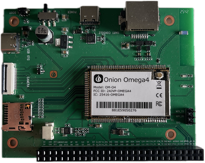
Key Connectors & Components
- USB (Serial Debug Port) — top edge; primary interface for console access.
- USB OTG Port — left side; supports host or device mode.
- BOOT Button — top-left corner; hold during reset to enter firmware flashing mode.
- Power Switch — to the right of the BOOT button.
- microSD Slot — left edge, below the OTG port.
- Ethernet Port (100 Mbps) — top-right edge.
- GPIO Header — bottom edge; exposes GPIO, I²C, SPI, etc.
- Microphone Input & Speaker Output — above the GPIO header.
- On-board LED — tied to a GPIO pin (see GPIO test below for usage).
- Single dual-band surface-mount antenna — covers 2.4 and 5 GHz Wi-Fi.
3. What You Need
- Omega-4 Evaluation Board (EVB) with the bundled dual-band antenna installed (no second antenna required).
- USB-A to USB-Micro/USB-C cable (depends on the serial port connector on your EVB).
- 5 V / 2 A power supply if not powering directly from a computer USB host port (host power works for bring-up).
- Ethernet cable (optional but recommended).
- Access to a Wi-Fi network for station-mode testing.
- Terminal program (PuTTY, minicom, screen, etc.).
4. Power-Up & Serial Console Access
4.1 Connect the Serial Debug Port
- Plug the USB cable into the Serial Debug USB port on the top edge.
- On your host machine, open your terminal program with:
- Device:
/dev/ttyUSB*(serial console is exposed only as a USB-UART interface). - Baud rate: 115200
- 8-N-1 settings
- Device:
- Switch Power ON.
You should see the boot logs followed by the Linux shell prompt:
Omega-4 login:
5. Network Bring-Up (OpenWrt Standard Configuration)
The Omega-4 uses the standard OpenWrt UCI configuration system. You can apply changes using uci commands or by editing /etc/config/network and /etc/config/wireless.
5.1 Verify Ethernet Connectivity
Check that the Ethernet interface exists:
ip link show eth0
Configure Ethernet as a DHCP client using the bridge device (br-lan):
uci set network.@device[0]=device
uci set network.@device[0].name='br-lan'
uci set network.@device[0].type='bridge'
uci set network.@device[0].ports='eth0'
uci set network.lan=interface
uci set network.lan.device='br-lan'
uci set network.lan.proto='dhcp'
uci commit network
/etc/init.d/network restart
Test connectivity:
ping -c 5 openwrt.org
If you receive replies, Ethernet is working correctly.
6. Wi-Fi Test (Station Mode)
6.1 Enable and configure Wi-Fi (OpenWrt)
Bring up the radio interface and scan for networks (requires the interface to be up):
ip link set wlan0 up
iw dev wlan0 scan
Configure station mode (replace <SSID> and <PASSWORD>):
uci set wireless.radio0.disabled='0'
uci set wireless.@wifi-iface[0].mode='sta'
uci set wireless.@wifi-iface[0].ssid='<SSID>'
uci set wireless.@wifi-iface[0].key='<PASSWORD>'
uci set wireless.@wifi-iface[0].encryption='psk2'
uci commit wireless
wifi
Define the DHCP interface if needed:
uci set network.wwan=interface
uci set network.wwan.proto='dhcp'
uci commit network
ifup wwan
Verify IP assignment:
ip addr show wlan0
Test internet connectivity:
ping -c 5 google.com
7. Blink LED
The current EVB firmware exposes one LED class device called sys. LED triggers are kernel-driven patterns (heartbeat, timer, netdev, etc.). Brightness is direct, immediate control when triggers are set to none.
List the LED and see available triggers (max brightness is 1 on this build):
ls /sys/class/leds
cat /sys/class/leds/sys/trigger    # [none] timer heartbeat default-on netdev mmc1 mmc2
cat /sys/class/leds/sys/max_brightness
Pick a trigger first if you want automatic behavior (example: heartbeat):
LED=/sys/class/leds/sys
echo heartbeat > $LED/trigger
For manual on/off control, clear the trigger and write brightness:
echo none > $LED/trigger
echo 1 > $LED/brightness   # on
echo 0 > $LED/brightness   # off
Seeing the LED blink (heartbeat) or toggle (manual) confirms the driver is working.
8. Firmware Releases
Download firmware images from the official releases page: https://github.com/OnionIoT/openwrt-omega4/releases.
9. Conclusion
You now have a powered Omega-4 Evaluation Board with working serial console access, verified Ethernet and Wi-Fi connectivity, and a simple GPIO LED toggle. For deeper hardware details—pinouts, electrical specs, peripheral buses—refer to the Omega-4 Hardware Reference Manual and the SOM Integration Guide.